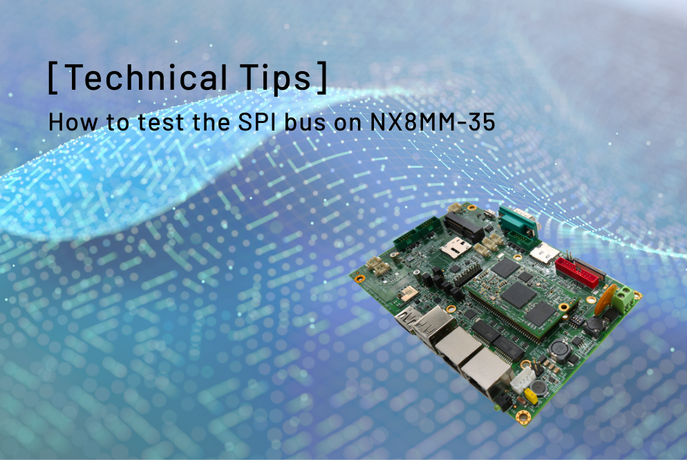
This article will tell you how to test the SPI bus on the NX8MM-35 in Yocto Linux.
The SPI bus is an optional feature supported on ICOP’s NX8MM-35, and it shares functionality with UART3 on the board.
在以下提示中,我們將逐步提供指引。
您需要的工具:
- NX8MM-35 (Find it 此處)
- Yocto Linux 4.0:映像檔 / 指南
- USB to micro USB cable for restoring image.
- SPI Testing file (Put it in a USB disk): link
- A testing wire to test SPI bus self-transmitting.
![[Technical tips] How to test the SPI bus on NX8MM-35](https://www.icop.com.tw/datas/upload/files/NEWS/Resources/How%20to%20test%20the%20SPI%20bus%20on%20NX8MM-35/testingwire.jpg "[Technical tips] How to test the SPI bus on NX8MM-35")
- Soldering iron for switching UART3 function to SPI bus.
Switching the UART3 to SPI bus on NX8MM-35.
On NX8MM-35, the UART3 and SPI bus can be switched by modifying the resistor on the board.
Please follow the image below and use the soldering iron to move the 0 ohm resistor to the correct location.

Test the SPI function in Yocto Linux.
![[Technical tips] How to test the SPI bus on NX8MM-35](https://www.icop.com.tw/datas/upload/files/NEWS/Resources/How%20to%20test%20the%20SPI%20bus%20on%20NX8MM-35/boardoutlinewithwire.jpg "[Technical tips] How to test the SPI bus on NX8MM-35")
./spidev_test -D /dev/spidev3.0 -v -p xxx
In this case, we type ./spidev_test -D /dev/spidev3.0 -v -p SPITESTING, and if the test succeed, it will show the “SPITESTING” in the test result.
- Plug testing wire to the J12 (SPI bus) on NX8MM-35.
- Plug the USB disk with SPI testing application in the NX8MM-35 and turn it on; then open the terminal in Yocto Linux.
- Mount the USB to Lunix and access the USB file.
- Run below command in the USB file:
For the steps above, you could find all of the information in the image below:

Check the video:

主要特點 NX8MM-35:
- NXP i.MX8M Mini,四核 1.6GHz ARM Cortex-A53 處理器
- 2/4GB LPDDR4 onboard
- COM / 2U / GLAN / Audio / eMMC / MiniPCIe
- 9″ TFT 1024×600 解析度 LCD,搭配電阻式觸控螢幕
- 工作溫度: 0 ~ +60°C
- eMMC-16GB 板載
- Micro SIM 卡座的 MiniPCIe 插座
- 寬電壓輸入,+12~36Vdc
- 無線區域網路 & 藍牙
如果想了解相關資訊及需求,請點選訊息於此處 info@icop.com.tw,或致電離您最近的 ICOP 分公司,或聯繫我們的 全球官方經銷商。

![[Technical Tips] Upload the LCD BIOS by using the batch file to the VDX boards](https://icop-shop.com/wp-content/uploads/2026/02/Technical-Tips-Upload-the-LCD-BIOS-by-using-the-batch-file-to-the-VDX-boards-300x201.png)
![[Technical tips] Start Guides for QEC-M-01 and SANYO DENKI SANMOTION G Series (CSP PP)](https://icop-shop.com/wp-content/uploads/2026/02/Technical-tips-Start-Guides-for-QEC-M-01-and-SANYO-DENKI-SANMOTION-G-Series-CSP-PP-300x201.png)